3D printers are incredible tools capable of bringing amazing creations to life. However, the journey of 3D printing isn’t always smooth. Encountering issues is a common part of the process, and whether you are dealing with filament over extrusion or unwanted blobs marring your print surface, a range of problems can arise. The positive aspect is that the majority of these 3D printing challenges have straightforward solutions, often not requiring extensive technical knowledge or the purchase of new equipment.
This article will walk you through seven frequently encountered 3D printing problems, providing effective solutions to help you master your 3D printing endeavors and achieve successful prints.
Let’s dive in and explore these common issues and their fixes.
1. Understanding and Resolving Under and Over Extrusion
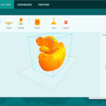
 Example of under extrusion in a 3D print
Under extrusion, image depicting gaps between printed lines, highlighting a common 3D printing defect. Credit: Ultimaker Support
Under extrusion occurs when your 3D printer fails to dispense a sufficient amount of filament. This results in noticeable gaps between the printed lines, particularly in the perimeter walls and infill areas of your 3D model. This issue not only degrades the visual quality of your prints but can also significantly weaken the structural integrity of the printed parts, making them prone to mechanical failures under stress.
Conversely, over extrusion happens when the 3D printer pushes out too much plastic. This excess material leads to a buildup, often causing prints to appear melted or distorted, with a loss of dimensional accuracy and surface finish.
The Root Causes
The primary culprit behind both under and over extrusion is often an incorrectly configured extrusion multiplier. This setting within your slicing software dictates the rate at which your 3D printer extruder pushes filament through the nozzle. If this value is not calibrated correctly for your specific filament and printer setup, it can lead to either insufficient or excessive material flow.
Another frequent cause is using the wrong filament diameter setting in your slicer. If the software is set to a different diameter than the filament you are actually using, it will miscalculate the material flow, leading to extrusion problems and impacting layer adhesion.
Effective Solutions
To address under or over extrusion, the first step is to adjust the extrusion multiplier in your slicing software. Incrementally increase the multiplier to combat under extrusion, or decrease it to resolve over extrusion. Small adjustments are key; usually, changes in increments of 0.05 are sufficient to observe noticeable improvements.
Equally important is ensuring that your filament diameter setting in the slicing software matches the actual diameter of the filament you are using. Most common filaments are 1.75mm or 2.85mm in diameter. Verify the specification of your filament and adjust the setting in your software accordingly to ensure accurate material flow calculation.
2. Eliminating Stringing: Achieving Clean 3D Prints
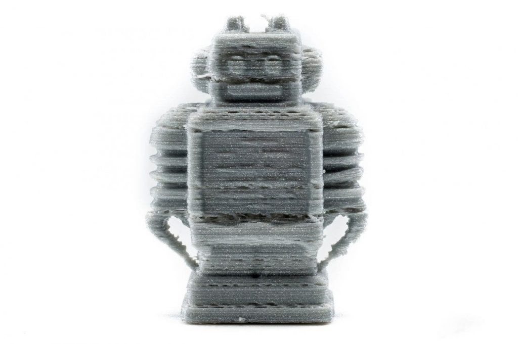
 Example of stringing in a 3D print
3D printing stringing issue, showcasing fine strands of plastic between printed parts, a common 3D printing artifact. Credit: All3DP
Stringing, sometimes referred to as “hairy prints,” is a common annoyance in FDM 3D printing, particularly when printing at higher temperatures. It manifests as thin strands of plastic webbing or “strings” left behind by the nozzle as it moves between different parts of a print. This occurs when molten plastic oozes from the nozzle during travel moves, leaving these unwanted traces across the print. Besides detracting from the aesthetic appeal of the print, stringing also wastes filament and can increase overall printing costs.
Stringing is more pronounced when printing models with intricate details or multiple separated parts, as these designs necessitate more travel movements of the print head, providing more opportunities for oozing and string formation.
Understanding the Causes
The most frequent cause of stringing is incorrect retraction settings. Retraction is the process where the 3D printer pulls back the filament slightly when the nozzle moves between print sections to prevent plastic from oozing out. If the retraction distance (how much filament is pulled back) or retraction speed (how quickly it’s pulled back) are not optimally configured, stringing is likely to occur.
Another significant factor is an excessively high extruder temperature. When the nozzle temperature is too high, the thermoplastic filament becomes more fluid and prone to oozing, even with retraction enabled.
Implementing Solutions
Begin by examining and adjusting your retraction settings in your slicing software. Experiment with increasing the retraction distance and speed. Start with small increments, like increasing the retraction distance by 1mm at a time, and test print to observe the effect. Finding the right balance for your specific filament and printer is crucial.
If retraction adjustments aren’t fully resolving the issue, consider lowering your extruder temperature. Even if you are using recommended temperatures from the filament manufacturer, your specific 3D printer’s temperature readings might vary. Reduce the temperature in small steps (e.g., 5°C increments) and test print after each adjustment until stringing is minimized.
Furthermore, the type of filament itself can influence stringing. Some materials, like PLA, are known to be more prone to oozing and stringing compared to others like ABS. If you are consistently struggling with stringing, consider experimenting with different filament types or brands, as some formulations are designed to reduce oozing.
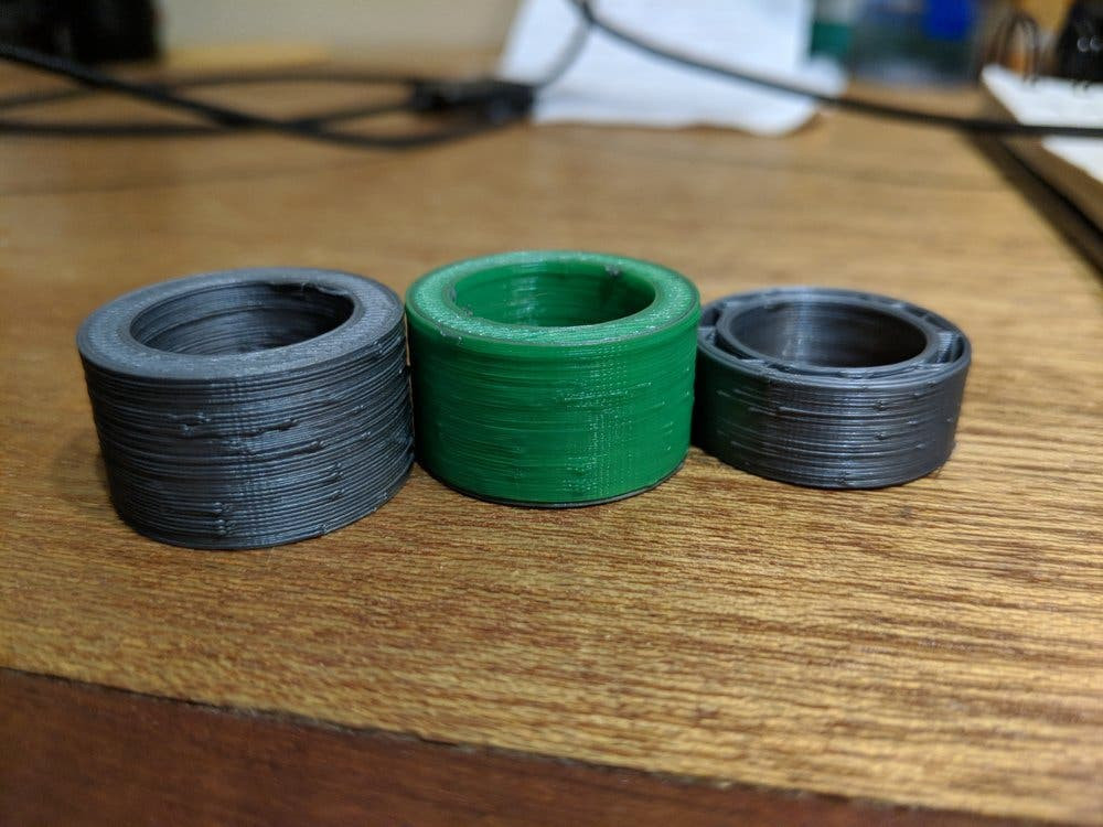
3. Overcoming Layer Separation and Splitting in 3D Prints
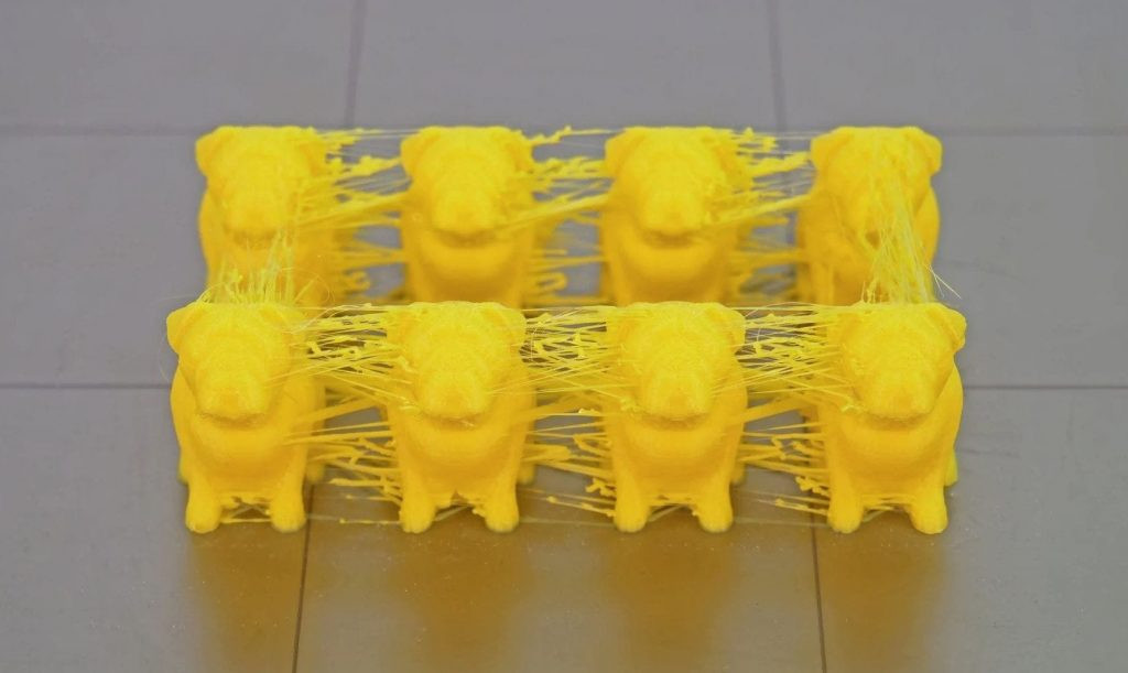
 Example of layer separation in a 3D print
3D printing layer separation issue, showing distinct gaps between layers of a printed object, compromising structural integrity. Credit: Simplify3D
Layer separation, also known as layer splitting, is a critical 3D printing problem where printed layers fail to properly adhere to each other, resulting in visible cracks or splits along the layer lines. This issue can occur during the print process, leading to print failure and material waste. Successful 3D printing relies heavily on strong inter-layer adhesion, ensuring each new layer bonds seamlessly to the layer beneath it. When this adhesion is compromised, parts can separate, warp, and lose structural integrity.
Identifying the Causes
A common cause of layer separation is setting an excessive layer height. Layer height is the vertical thickness of each printed layer. If the layer height is too large relative to the nozzle diameter, the layers may not have sufficient surface contact to bond effectively. Ideally, the layer height should be a fraction of the nozzle diameter to ensure proper layer squish and bonding.
Another significant factor is insufficient print temperature. Printing at temperatures that are too low for the material being used hinders the thermoplastic’s ability to properly melt and fuse with the previous layer. This is especially relevant when switching between different filament types or trying new brands, as each material has its optimal temperature range for bonding.
Implementing Solutions
Refine your layer height settings in your slicing software. A general guideline is to aim for a layer height that is approximately 20% smaller than your nozzle diameter. For example, with a 0.4mm nozzle, a layer height of 0.32mm or lower is recommended. Experiment by reducing the layer height to increase layer adhesion and see if it resolves the separation issue.
If temperature is suspected, try incrementally increasing your print temperature. Small increments of 3-5°C are generally safe for most rigid thermoplastics. Monitor the print quality and layer adhesion as you increase the temperature. Refer to the filament manufacturer’s recommended temperature range as a starting point, but be prepared to fine-tune based on your printer and environment.
Additionally, consider the ambient temperature of your printing environment. If you are printing in a cold room or if there are drafts, it can affect layer adhesion, especially for temperature-sensitive materials like ABS. If your printer has an enclosure or heated chamber, utilizing it can help maintain a more stable and warmer environment, promoting better layer bonding. Increasing the chamber temperature by even 5°C can sometimes make a significant difference.
4. Addressing Blobs and Zits on 3D Print Surfaces
 Example of blobs and zits on a 3D print surface
3D printing blobs and zits issue, showing irregular bumps and imperfections on the surface of a printed object, impacting surface finish. Credit: Ultimaker Community
Surface quality is often a primary factor in judging the success of a 3D print. Blobs and zits are surface defects that appear as small bumps or imperfections on the exterior of your 3D printed object. These blemishes can detract from the aesthetic appeal and are often seen as indicators of either a poorly calibrated 3D printer or suboptimal print settings. However, it’s important to note that blobs and zits are common issues that can affect even experienced users and high-quality printers, as they are often related to specific print settings and printer mechanics.
Blobs and zits can sometimes become more pronounced after starting and stopping a print due to variations in extruder behavior during start-up and shut-down phases.
Identifying the Causes
Retraction and coasting settings are frequently linked to the formation of blobs and zits. If these surface imperfections appear predominantly at the start and end points of each perimeter layer, it suggests that your retraction settings need adjustment. The retraction settings control how the extruder handles filament flow when moving between print paths, and improper settings can lead to excess material being deposited at these points.
If your 3D printer uses a Bowden extruder setup (where the extruder motor is located away from the hot end), excessive retraction can sometimes exacerbate blob and zit formation. In some cases, reducing retraction or even disabling it entirely might be beneficial in Bowden systems, although this might introduce stringing (which was discussed earlier).
Implementing Solutions
Fine-tuning your retraction settings is usually the first step in mitigating blobs and zits. Experiment with adjusting the retraction distance and speed. Slightly reducing the retraction distance can sometimes prevent excess material from being drawn back and then re-extruded inconsistently, leading to blobs.
Coasting is another setting in slicing software that can help minimize blobs and zits. Coasting instructs the extruder to stop extruding material slightly before the end of a perimeter path. The residual pressure in the nozzle then continues to extrude just enough material to complete the path, reducing over-extrusion at the stopping point. Activating or adjusting the coasting settings can be effective in smoothing out surface imperfections.
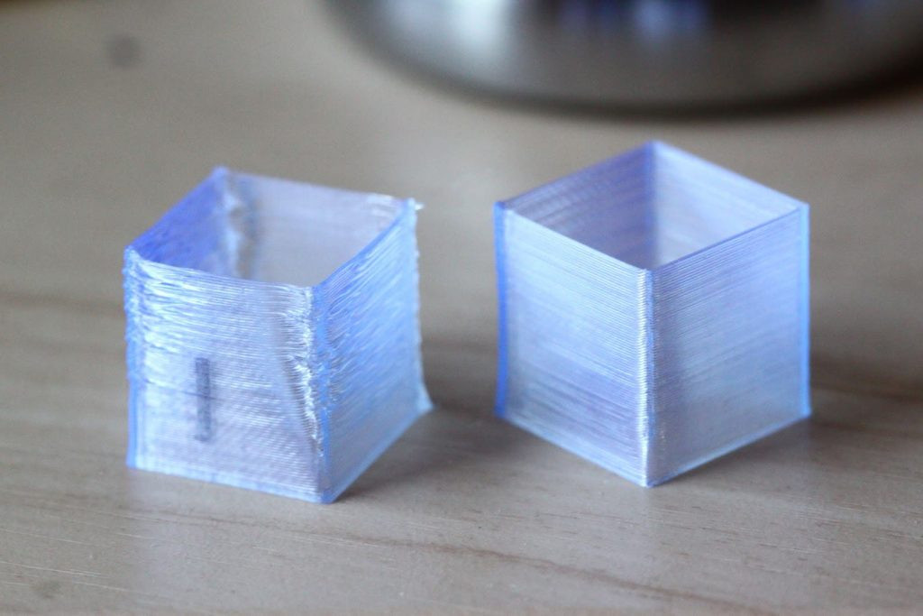
5. Preventing Curling and Rough Corners in 3D Prints
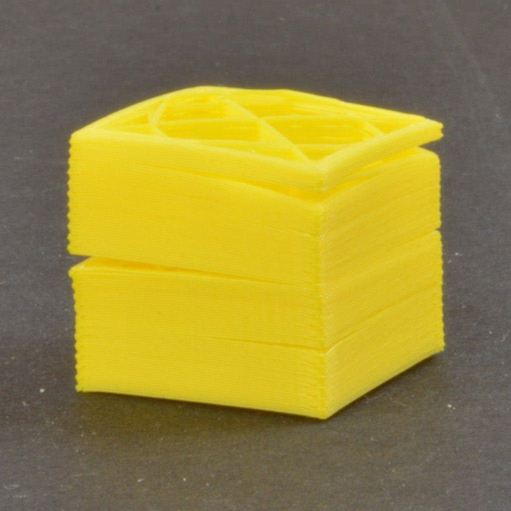
 Example of corner curling in a 3D print
3D printing corner curling issue, depicting warped and lifted corners of a printed object, often seen with certain materials. Credit: 3D Printing Stack Exchange
Curling and rough corners are common problems, particularly when 3D printing with filaments that require higher temperatures, such as ABS or ASA. This issue manifests as the corners and edges of your printed part lifting or curling upwards away from the build platform, resulting in deformed and rough edges. This warping occurs because the cooling process of the extruded plastic is not uniform, leading to internal stresses and deformation as the material solidifies.
Understanding the Causes
Curling and rough corners primarily arise when the 3D printing environment or chamber fails to cool the printed layers rapidly and uniformly enough. High-temperature filaments remain more pliable and susceptible to deformation in a warm environment if they are not actively cooled.
Another significant cause of curling is insufficient adhesion of the printed part to the build platform. If the first layer does not adhere firmly to the bed, the subsequent layers are more likely to warp and curl, as the lack of bed adhesion introduces mechanical stress within the printed layers.
Implementing Solutions
Improving layer cooling is crucial to combat curling. If you are using a printer with a heated chamber, consider reducing the chamber temperature to promote faster cooling of each layer. Alternatively, adjusting the extrusion temperature itself to a slightly lower setting can also help the filament solidify more quickly after being extruded.
Enhancing bed adhesion is equally important. Ensure that your build platform is properly leveled and calibrated. Use appropriate bed adhesion methods such as using a heated bed, applying adhesive substances like glue stick or hairspray (depending on the material), or utilizing build surfaces designed for better adhesion, like PEI or BuildTak.
If curling occurs primarily during the initial layers of printing, it could indicate that your build platform is not perfectly level or that the first layer is being printed too quickly. Re-leveling your bed and reducing the first layer print speed can significantly improve initial layer adhesion and prevent warping.
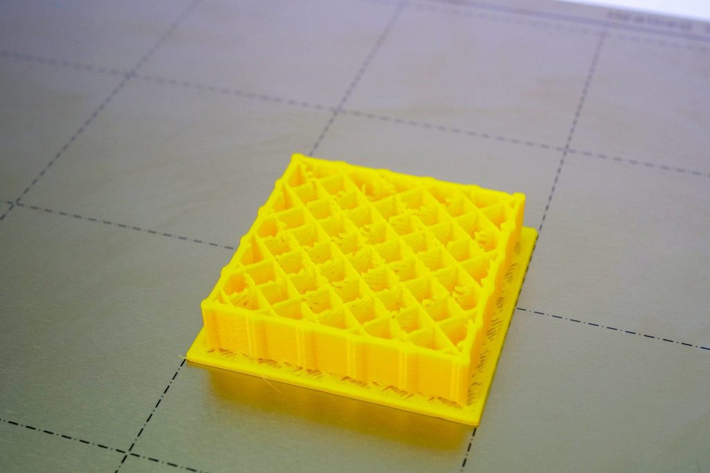
6. Strengthening Weak Infill in 3D Prints
 Example of weak infill in a 3D print
3D printing weak infill issue, showing sparse and fragile internal support structure within a printed object, affecting overall strength. Credit: PrusaPrinters Blog
Infill is the internal structure of a 3D printed part and plays a vital role in determining its overall strength, rigidity, and weight. Infill acts as a network of support within the outer shell of the print, connecting the surfaces and creating a semi-solid model. Weak or inadequate infill can compromise the dimensional accuracy and structural integrity of your 3D prints, making them more susceptible to breakage or deformation under load.
Addressing infill problems early is essential to prevent material waste and ensure that your 3D printed models perform as intended, especially for functional parts or prototypes that require mechanical strength.
Understanding the Causes
Sometimes, 3D printers struggle to properly form infill patterns, particularly complex ones, when printing at high speeds. Excessive print speeds can overwork the extruder, leading to inconsistent material deposition and weak infill structures.
Another contributing factor is using infill settings with very thin walls or low density. While reducing infill density and wall thickness can save material and print time, it can also significantly weaken the infill structure, making it fragile and prone to collapsing or failing under stress.
Implementing Solutions
Experiment with using different infill patterns. Slicing software offers a variety of infill patterns, each with different structural characteristics. Grid, triangular, honeycomb, cubic, and rectilinear infill patterns are generally robust and well-supported by most 3D printers. Try switching to a different infill pattern to see if it improves infill quality and strength.
Increasing the infill wall thickness or density can also significantly strengthen the infill structure. While this will increase print time and material usage, it will result in a more solid and durable infill. Consider increasing the infill percentage or adjusting settings to create thicker infill walls.
Lowering the print speed, especially for the infill sections, can also help. If you are attempting to print infill too quickly, the extruder might struggle to keep up with the desired flow rate, leading to weak or incomplete infill. Reducing the infill print speed gives the extruder more time to accurately deposit material and create a stronger infill structure.
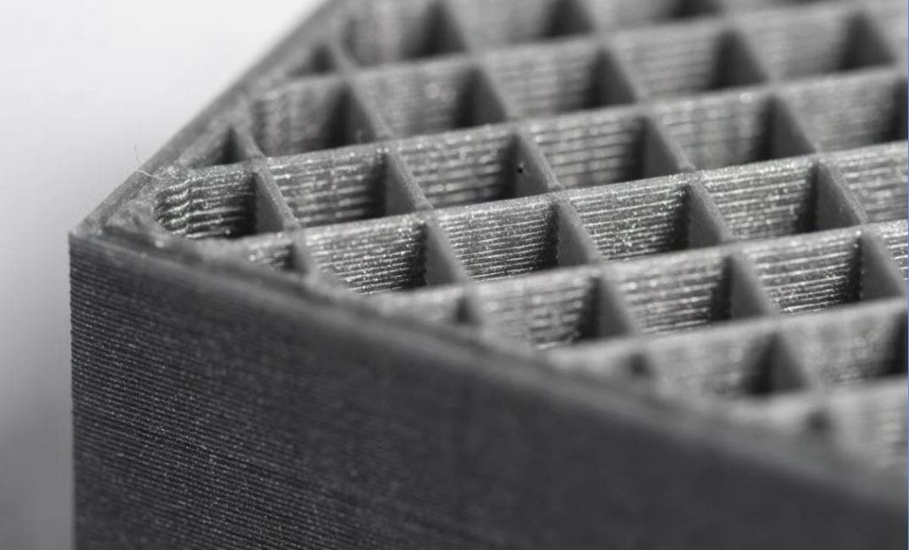
7. Resolving Gaps Between Infill and Outline in 3D Prints
 Example of gaps between infill and outline in a 3D print
3D printing infill outline gaps issue, showing visible spaces between the inner infill structure and the outer perimeter walls of a printed object, affecting aesthetics and strength. Credit: All3DP
Gaps between the infill and outline (perimeter walls) of a 3D print are arguably one of the most visually unappealing 3D printing mishaps. These gaps indicate a lack of proper bonding or overlap between the infill structure and the outer shell of the printed part. This issue not only affects the aesthetics of the print but also compromises its mechanical strength, as the gaps represent weak points that can lead to structural failure.
Ensuring a strong bond between the infill and outline is crucial for both visual appeal and mechanical performance. Gaps act as stress concentrators and can significantly reduce the overall durability and functionality of the 3D printed object.
Understanding the Causes
The most common cause of gaps between infill and outline is an incorrect infill overlap setting in your slicing software. The infill overlap parameter determines how much the infill pattern extends into the perimeter walls. If this setting is configured too low, it results in insufficient material being placed at the interface between the infill and outline. As the plastic cools and shrinks, this lack of overlap causes the infill to pull away from the outline, creating gaps.
Printing at excessively high speeds can also contribute to infill and outline separation. When the infill is printed much faster than the outline, it doesn’t have enough time to properly bond to the perimeter walls. This rapid printing can lead to shrinkage and separation as the materials cool down at different rates.
Implementing Solutions
Adjust the infill overlap setting in your 3D printing software. This setting is typically represented as a percentage. For instance, an infill overlap of 12% means that the infill will extend 12% into the inner perimeter wall. Increasing this percentage value will increase the amount of overlap, promoting better bonding between the infill and outline. Experiment by increasing the overlap in small increments (e.g., 5-10% increases) and test print to observe the improvements.
If the infill overlap setting is already adequately configured, consider reducing your print speed, particularly for the infill sections. If you are printing the infill significantly faster than the outline, try reducing the infill print speed to allow more time for the infill to bond with the perimeter walls. Finding a balanced print speed for both infill and outline is key to achieving strong layer adhesion and eliminating gaps.
By understanding these common 3D printing problems and applying the suggested solutions, you can significantly improve your print quality, reduce material waste, and achieve more consistent and successful 3D printing outcomes.