Organizing tools efficiently is crucial for any workshop or DIY enthusiast. Recently, I embarked on a 3D printing project to customize socket organizers for my tool bag, specifically for four socket sets that accompany my 3/8” impact wrench. The goal was to create a 3d Print Socket Organizer solution that would securely hold sockets in place while enduring the rigors of being carried in a tool bag.
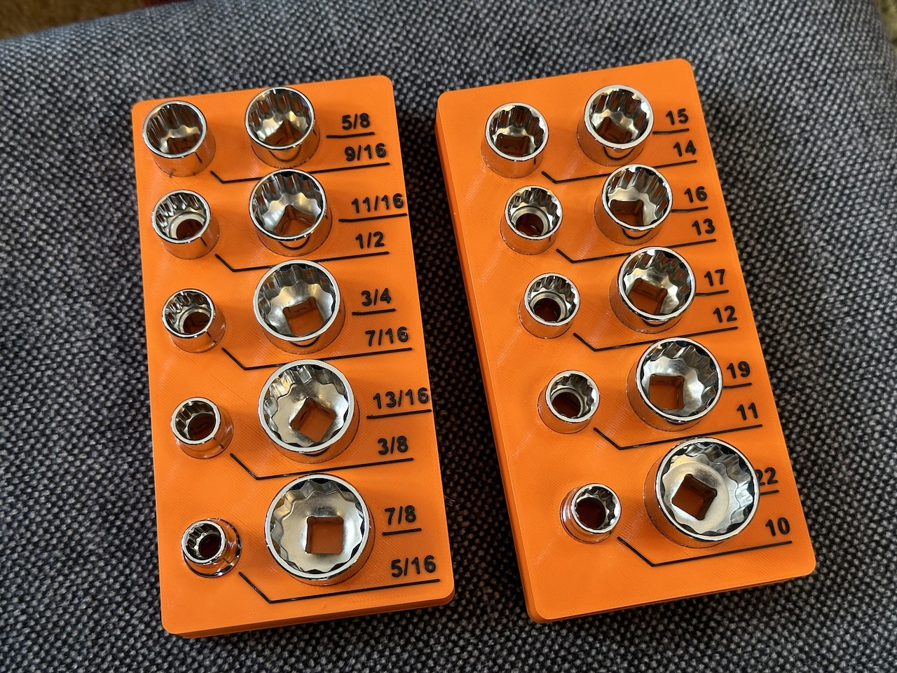 Two of the four socket organizers I printed
Alt: Close-up of two black 3D printed socket organizers, showcasing the snug fit of sockets within the custom-designed slots.
Unlike organizers designed for stationary drawers, these tool bag organizers demanded a snug friction fit. Sockets needed to stay firmly in place during transport but still be easily removable by hand when needed. This presented a familiar challenge, reminiscent of creating 3D printed end caps for aluminum extrusions – achieving that Goldilocks zone of just right friction.
For this project, and similar applications requiring durability and flexibility, I opted to print with 95A TPU filament. The inherent softness and semi-flexible nature of TPU seemed ideal for withstanding the stresses of frequent use and achieving the desired friction fit.
However, the question remained: how can you reliably design and achieve optimal friction fits in 3D printed parts? While there are rules of thumb and design considerations, as you’ll discover, trial and error remains an essential part of the process.
The Nuances of Friction Fit Design in 3D Printing
Creating effective friction fits in 3D printing is less about rigid rules and more about understanding a complex interplay of factors. Let’s delve into the key considerations that influence the success of your 3D printed friction fit designs.
Offset: Finding the Right Gap
One of the first questions when designing for friction fit is determining the appropriate offset in your CAD software. How much smaller should your 3D printed part be compared to the object it’s intended to fit onto? Unfortunately, there’s no magic number. The optimal offset is heavily influenced by a multitude of factors we’ll explore here, and even some you might not initially consider.
As a starting point, based on the size and measurement accuracy of the parts involved, I typically begin with an offset between 0.05mm and 0.2mm. This range provides a good baseline for experimentation and adjustment.
Diameter vs. Offset in CAD: A Crucial Distinction
It’s vital to understand the difference between specifying an offset and adjusting the diameter of a circle in your CAD software. For example, setting a 0.1mm offset from a circle’s edge is not the same as increasing the circle’s diameter by 0.1mm. Increasing the diameter by 0.1mm only results in a 0.05mm offset from the original edge. Being precise with your CAD adjustments is key to controlled friction fit design.
 Autodesk Fusion sketch demonstrating offset vs. diameter adjustment
Alt: Screenshot from Autodesk Fusion 360 illustrating the difference between applying an offset and adjusting the diameter of a circular sketch for 3D printing design.
Interface Surface Area: The Grip Factor
The surface area where two parts make contact plays a significant role in the overall friction and holding power of the fit. A larger interface surface area generally translates to a more secure fit, and conversely, a smaller surface area demands tighter tolerances and greater precision in your design.
This principle became particularly evident in another recent project: designing 3D printed friction-fit lens caps for camera lenses. For a small lens with a diameter of approximately 25mm, the lens cap had a minimal interface surface area. Achieving a good fit required almost ten design iterations with sub-millimeter adjustments.
In contrast, a lens with a larger diameter of around 51mm, offering a significantly greater interface surface area, required only a couple of iterations to achieve a perfectly functional lens cap. The increased surface area provided more forgiveness in tolerances. To compensate for small interface areas, consider adding internal contact surfaces or increasing the height of the friction feature, as I did with the extrusion end caps, to maximize contact and improve fit reliability.
Wall Thickness: Flexibility and Fit
Especially when using flexible filaments like TPU, the thickness of the printed wall significantly impacts the “give” and flexibility of the part. A wall printed with multiple perimeters (three or more) will be considerably less flexible than a single-perimeter wall. This difference in flexibility needs to be factored into your offset calculations. A thicker wall might require a slightly larger offset to achieve the same friction fit as a thinner, more flexible wall. This consideration should be balanced with the structural strength requirements of the part, which often dictate the choice of wall loop count, and is also influenced by your nozzle diameter.
Careful Measurement: Precision is Paramount
Accurate and meticulous measurement of the objects involved in the friction fit is absolutely crucial. While larger parts with larger interface areas offer some leniency, precision remains paramount. For projects like these socket organizers and the aforementioned lens caps, I relied on high-quality calipers to measure objects to within 0.05mm accuracy.
For larger, less critical parts, such as the extrusion end caps, modeling the profile to within approximately 0.2mm of accuracy proved sufficient. However, for tighter friction fits and smaller parts, investing in accurate measurement tools and techniques is essential.
Printer Dimensional Accuracy: Understanding Your Machine’s Limitations
Dimensional accuracy in 3D printing is a known challenge. Numerous variables influence how accurately your 3D printer reproduces your designs. These factors include printer quality, the level of calibration (both user and factory), filament material, nozzle size, and print settings.
To mitigate dimensional inaccuracies, careful calibration for specific material, nozzle, and print setting combinations is crucial. Slicer software settings can be adjusted to compensate for dimensional deviations. Alternatively, you can directly adjust dimensions and offsets within your CAD software to pre-compensate for printer tendencies. Furthermore, strategically orienting your object on the print bed can minimize error in critical dimensions.
Material Contraction and Warping During Printing: Accounting for Material Behavior
As 3D printed plastic cools, it undergoes contraction and may warp, impacting the final dimensions and fit of your parts. This behavior is influenced by several factors: filament type, layer height, hotend and bed temperatures, chamber temperature, cooling fan settings, volumetric flow rate, wall thickness, and infill type and density.
Similar to dimensional accuracy, contraction and warping can exhibit anisotropy, meaning they may differ along the X, Y, and Z axes. You might be able to leverage this directional behavior to your advantage by strategically orienting your part on the build plate to minimize distortion in the critical fit direction.
Materials: Material Properties Matter
The materials involved in the friction fit significantly influence the required tolerances. A friction fit between two TPU parts can typically tolerate looser tolerances compared to a fit between two rigid plastics. Achieving a secure fit between a smooth aluminum surface and even a soft TPU might necessitate tighter tolerances due to the material properties and surface interactions. Consider the hardness, flexibility, and surface finish of the materials when designing your friction fit.
Dust: An Environmental Factor
Consider the operating environment of your friction fit. Will dust or debris accumulate between the mating surfaces? (For parts designed for tools or workshop environments, like these socket organizers, the answer is often yes). The size and nature of the dust particles can either increase or decrease friction between the surfaces. In dusty environments, you might need to design for slightly looser tolerances to prevent binding due to dust accumulation.
Temperature & Thermal Expansion: Considering Temperature Swings
Finally, consider the temperature range the friction fit will be exposed to in its intended application. How much do the coefficients of thermal expansion differ between the materials involved? Significant temperature fluctuations can cause expansion and contraction, potentially affecting the tightness or looseness of the friction fit over time. For applications exposed to extreme temperature variations, you might need to design with materials that have similar thermal expansion coefficients or incorporate design features that accommodate thermal expansion.
Trial and Error: The Iterative Path to a Perfect Fit
Despite meticulous planning and consideration of all these factors, achieving a perfect friction fit often involves some degree of trial and error. The multitude of interacting variables makes precise prediction challenging. Ideally, this iterative process should be conducted using the same materials, interface surface area, print settings, and printer you intend to use for the final product to ensure accurate results.
To optimize this iterative process and minimize material waste, I often employ strategies to print test sections. For the socket organizers, I used Autodesk Fusion 360 to isolate and print a small section containing just a couple of socket slots. The rationale was that if two sockets fit correctly in the test section, the fit should be consistent across the entire organizer, assuming consistent measurements were taken for all sockets.
 The cut-out test section of a socket organizer in Autodesk Fusion
Alt: A digital cutout section of a 3D socket organizer design within Autodesk Fusion 360, used for test printing to evaluate socket fit.
This approach allowed for rapid iteration and refinement of the design without printing entire organizers for each test, saving both time and material.
The Result: Organized Sockets, Securely Stored
After navigating the design considerations and iterative testing, the resulting 3d print socket organizer proved to be a successful and practical solution. The TPU organizers provided the desired snug friction fit, securely holding the sockets within the tool bag while allowing for easy removal when needed.
For those interested in creating their own socket organizers, the STL files and OpenSCAD source files for these 3/8” socket organizers, specifically designed for Harbor Freight socket sets, are available.
(Interactive 3D viewer element would be embedded here as in the original article if possible)
The final socket organizers, now integrated into their tool bag, demonstrate the practical application of thoughtful friction fit design in 3D printing.
 The resulting 4 socket organizers at home in their tool bag
Alt: A tool bag interior view, showcasing four black 3D printed socket organizers neatly arranging socket sets within the bag.
In conclusion, designing for friction fits in 3D printing is a nuanced process that blends scientific understanding with practical experimentation. By carefully considering factors like offset, interface surface area, material properties, and printer characteristics, and embracing iterative testing, you can achieve robust and functional friction fit connections in your 3D printed projects, just like these 3d print socket organizer solutions.