
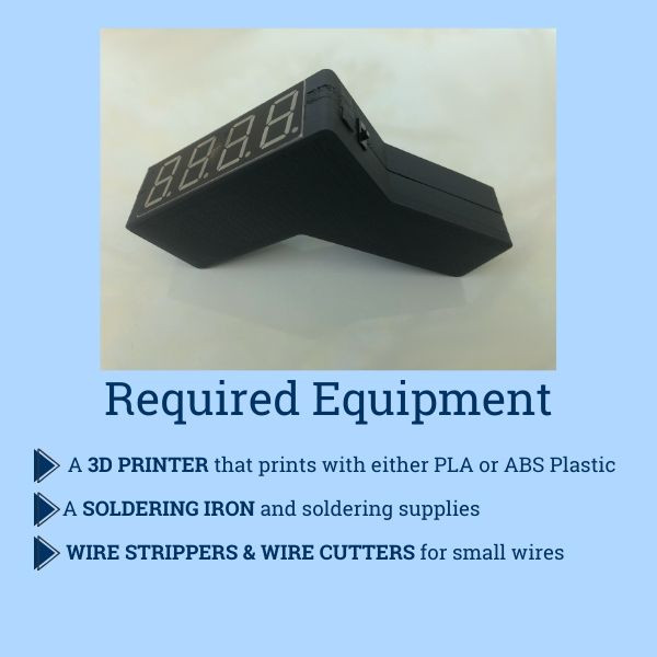
 Required equipment to build an infrared thermometer, including Arduino Pro Mini, resistors, pin headers, battery clip, temperature sensor, display, switch, pushbutton, protoboard, wires, battery, and FTDI board
As businesses and public spaces navigate reopening, non-contact temperature screening remains a crucial measure. However, the demand for infrared (IR) thermometers continues to outstrip supply. Researchers at the University of Maine’s VEMI Lab have developed this guide to empower hobbyists and makers to create their own reliable IR thermometers, leveraging 3D printing and readily available components. This project, sometimes referred to as the “Umaine Print Clip” thermometer due to its 3D-printed case and ease of assembly, can help local organizations implement health guidelines and safely reopen.
IMPORTANT DISCLAIMER: This DIY infrared thermometer is NOT for medical use. It is designed to provide an approximate temperature reading for initial screening purposes, helping to identify individuals who may have a fever. It should not be used for medical diagnosis or treatment decisions. For accurate medical assessments, always rely on certified medical devices and professional healthcare providers.
Parts You’ll Need for Your UMaine Print Clip Thermometer
Sourcing components for your DIY IR thermometer is straightforward. The parts listed below were selected for their balance of performance, availability, and suitability for embedding within a 3D-printed enclosure – a key feature of the “UMaine print clip” design. Prices are approximate and may vary; at the time of this guide’s publication, the total cost was around $60.
| Component | Description | Link |
|---|---|---|
| Arduino Pro Mini 328 | Microcontroller brain of the thermometer | https://www.sparkfun.com/products/11113 |
| 1K Ohm Resistors (20ct) | Resistors for LED display circuit | https://www.sparkfun.com/products/14492 |
| 10K Ohm Resistors (20ct) | Resistors for temperature sensor and button | https://www.sparkfun.com/products/14491 |
| Breakaway Pin Headers | For easy connections to Arduino | https://www.sparkfun.com/products/116 |
| Battery Clip | Connects 9V battery to the circuit | https://www.sparkfun.com/products/91 |
| Temperature Sensor | Infrared sensor to measure temperature | https://www.sparkfun.com/products/9570 |
| 7-Segment Display | Displays the temperature reading | https://www.sparkfun.com/products/11409 |
| On/Off Switch | Power switch for the thermometer | https://www.sparkfun.com/products/102 |
| Pushbutton | Trigger button to take a temperature reading | https://www.sparkfun.com/products/11995 |
| Protoboard | For prototyping and assembling the circuit | https://www.sparkfun.com/products/8808 |
| F/F Wires (20ct) | Female-to-female jumper wires for connections | https://www.sparkfun.com/products/12796 |
| 9V Battery | Power source for the thermometer | Local Store |
| FTDI Board** | Programmer for Arduino (optional, only 1 needed) | https://www.sparkfun.com/products/9716 |
**The FTDI board is optional and only one is required regardless of how many thermometers you build. See Step 4 for programming instructions with and without an FTDI board.
Why These Specific Components?
The selection of these components was carefully considered to optimize the DIY thermometer’s design. The Arduino Pro Mini stands out for its compact size without compromising reliability, making it ideal for embedding within a custom 3D-printed case, a key element of the “UMaine print clip” project. While pin headers, protoboard, and F/F wires aren’t strictly essential for basic functionality, they significantly enhance the robustness and ease of assembly of the final product. The 3D-printable case design is specifically tailored to accommodate the listed switch, pushbutton, and display; substituting these components may necessitate modifications to the case file.
It’s crucial to reiterate that the temperature sensor used in this guide is NOT medical-grade. The sensor specified offers an accuracy of ±0.5℃, whereas medical-grade sensors typically achieve ±0.1℃ accuracy. Therefore, emphasize again: DO NOT USE THIS THERMOMETER FOR MEDICAL DIAGNOSIS. Its purpose is solely for preliminary temperature screening to identify potential fever indicators, not for clinical evaluations.
For users seeking a sensor with slightly higher precision (though still not medical-grade), the MLX90614ESF-DCH-000-SP sensor from Digi-Key Electronics (https://www.digikey.com/product-detail/en/melexis-technologies-nv/MLX90614ESF-DCH-000-SP/MLX90614ESF-DCH-000-SP-ND/5414798) is an alternative.
Step-by-Step Instructions to Build Your IR Thermometer
Step 1: 3D Print the Thermometer Case
The “UMaine print clip” thermometer gets its name from its user-friendly, 3D-printed enclosure.
Download the 3D-printable case files here: https://bit.ly/2TxaxFv
The case is designed for easy 3D printing in two parts that securely clip together, simplifying assembly and eliminating the need for screws or complex fasteners. This “print clip” design makes the project accessible even for those new to electronics and 3D printing.
Recommended 3D printing settings:
- Layer Height: 0.2mm
- Infill Density: 10%
- Support Generation: Automatic (ON)
- Shells/Perimeters: 3
Start printing the first half of the case before beginning electronic assembly. 3D printing can take longer than assembling the components, so initiating the print early maximizes your time. Monitor the print periodically to ensure successful completion. Once the first half is printed, remove it and begin printing the second half.
Step 2: Download and Prepare the Arduino Code
Download the IR Thermometer Arduino code here: https://bit.ly/3cE2bUe
To program the Arduino Pro Mini, you’ll need the Arduino IDE software, available for free download at www.arduino.cc.
- Open the
IRThermometer.inofile in the Arduino software. - Access the Library Manager by navigating to “Sketch” > “Include Library” > “Manage Libraries” in the Arduino IDE toolbar.
- In the Library Manager search bar, type and install the following libraries:
SevSeg(for controlling the 7-segment display)Adafruit_MLX90614(for interfacing with the temperature sensor)
- Close the Library Manager after installing the libraries.
Step 3: Assemble the Electronic Components
This step involves assembling the electronic circuit for your “UMaine print clip” thermometer.
-
SCHEMATICS: Download and keep the datasheets for the components handy. These are crucial for correct wiring.
- Temperature Sensor Datasheet: https://bit.ly/2zltlkh
- 7-Segment Display Datasheet: https://bit.ly/3hgOHAv
-
WIRE PREPARATION: The F/F wires need slight modification for secure connections. For pin header connections, simply socket the wire as usual. For direct connections to component leads (like the display and temperature sensor), follow these steps:
a. Remove the black plastic casing from one end of an F connector by gently lifting the plastic tab above the metal connector.
b. With the plastic casing removed, insert the exposed metal pin into the female adapter.
c. Apply solder to the joint to create a robust and electrically sound connection, similar to soldering a wire directly to a component. -
PROTOBOARD USAGE: The protoboard’s internal connections are crucial to understand. Observe the green lines connecting groups of dots. These lines indicate connected contacts. Utilize these connected lines to link wires, resistors, and components effectively.
-
Prepare the Arduino Pro Mini: You will need the Arduino Pro Mini board and pin headers. (Figure 3)
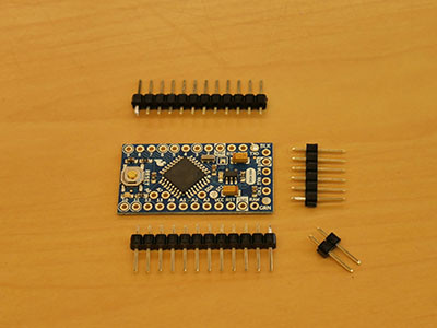 Arduino Pro Mini and pin headers for IR thermometer projectFigure 3
a. Break off two 12-pin, one 6-pin, and one 2-pin header strips from the breakaway pin headers.
b. Solder these pin headers to the Arduino Pro Mini board, ensuring they are straight and securely attached. (Figure 4)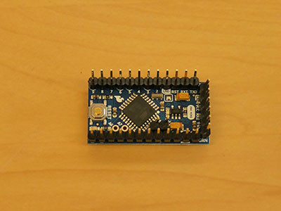 Soldered pin headers on Arduino Pro Mini for IR thermometer projectFigure 4
 -
Connect the 7-Segment Display: You’ll need 12 wires, the 7-segment LED display, four 1k Ohm resistors, and the protoboard. (Figure 5)
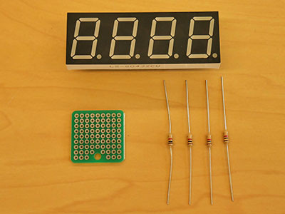 Components for connecting the 7-segment display: wires, display, resistors, protoboardFigure 5
a. Prepare 12 wires by removing the plastic jacket from one end of each wire as described in the “WIRE PREPARATION” section above. The prepared wire ends should resemble Figure 6.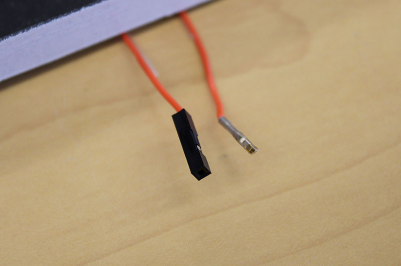 Prepared wire ends without plastic jackets for solderingFigure 6
b. Solder the non-jacketed end of each wire to each of the 12 pins on the 7-segment display. (Figure 7)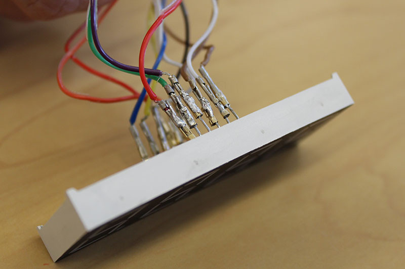 Wires soldered to the pins of the 7-segment displayFigure 7
c. For display pins 1-5, 7, 10, and 11, connect the jacketed end of the wire directly to the corresponding Arduino pin according to the schematic (Figure 2 in the original article).
d. For display pins 6, 8, 9, and 12, cut each wire in half. Solder one half of each wire to the protoboard. Solder a 1k Ohm resistor between this wire half and another point on the protoboard. Then, solder the remaining wire half from the resistor to the appropriate Arduino pin as per the schematic. (Figure 8) These resistors are current-limiting resistors for the display segments.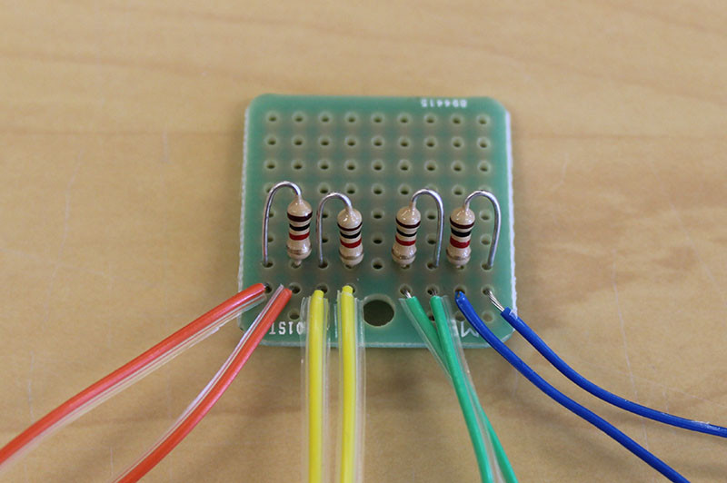 Resistors and wires connected to the protoboard for the 7-segment displayFigure 8
 -
Connect the Temperature Sensor and Pushbutton: You will need four 10k Ohm resistors, the temperature sensor, the pushbutton, and the protoboard from the previous step. (Figure 9)
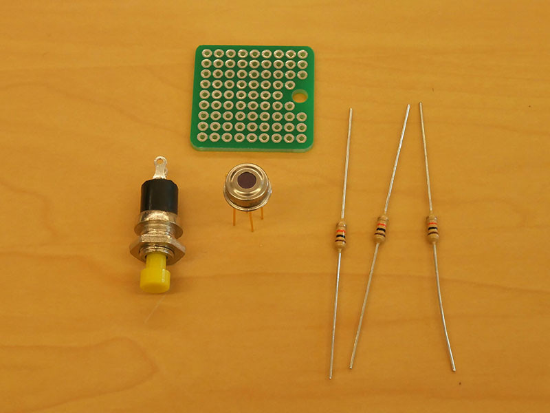 Components for connecting temperature sensor and pushbutton: resistors, sensor, button, protoboardFigure 9
a. Utilize the remaining space on the protoboard for this part of the circuit. Solder three 10k Ohm resistors to the protoboard and connect them at one end using the protoboard’s internal connections or solder bridges. These serve as pull-up resistors for the temperature sensor circuit. (Figure 10)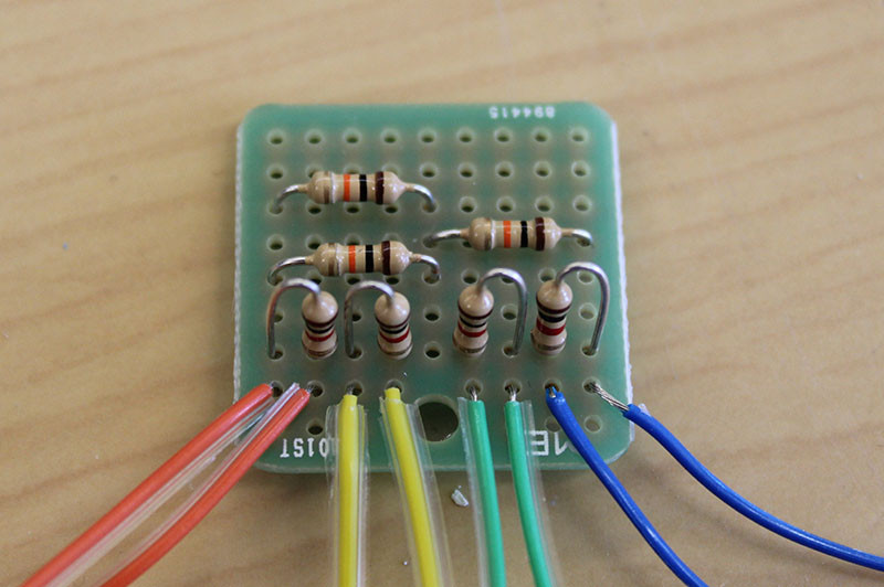 10k Ohm pull-up resistors soldered on the protoboardFigure 10
b. Solder wires to each of the temperature sensor’s legs. (Figure 11) Cut these wires in half. Solder both freshly cut ends of each wire to the protoboard as shown in Figures 12 & 13. The remaining open ends will connect to the Arduino according to the schematic (Figure 2).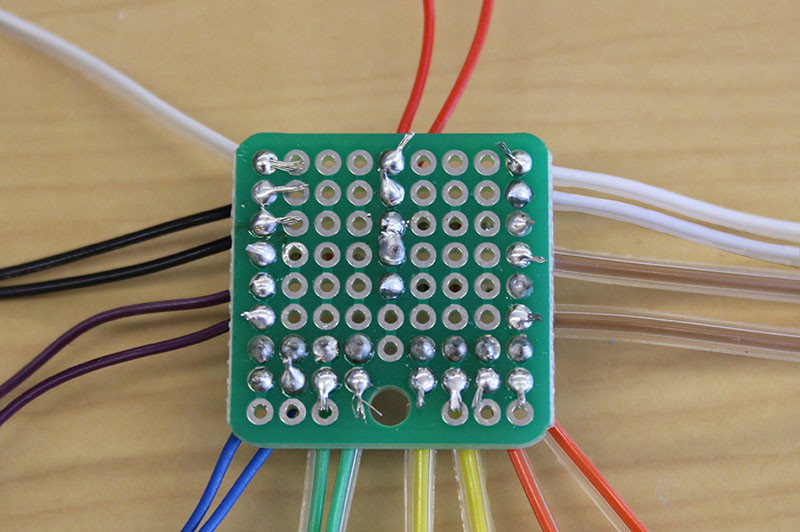 Temperature sensor wiring detail on protoboardFigure 13
i. Solder two wires to the free ends of two of the 10k Ohm resistors. Connect the jacketed ends of these wires to the SDA and SCL pins on the Arduino (for I2C communication with the sensor).
ii. Solder a wire to the common connection point of the 10k Ohm resistors. Connect the jacketed end to the VCC pin on the Arduino (power supply).
iii. Solder a wire to an open, connected section of the protoboard and connect the jacketed end to the GND pin on the Arduino (ground).
c. IMPORTANT: Refer to the temperature sensor datasheet (Figure 14) to ensure correct pin identification. Note that the pinout diagram is typically viewed from the top of the sensor.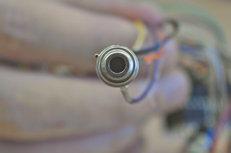 Temperature sensor pinout diagram for referenceFigure 14
 -
Connect the Pushbutton: To connect the pushbutton, cut a wire in half and remove the female connectors from both cut ends. Solder one wire between the third 10k Ohm resistor and one terminal of the pushbutton. Solder the other wire between the other pushbutton terminal and a ground point on your protoboard. Solder another wire to a contact connected to the third 10k Ohm resistor and connect its other end to pin A2 on the Arduino.
-
Connect the Battery Clip and Switch: You’ll need a battery clip and the on/off switch.
a. Cut the red wire on the battery clip. Solder each half of the cut red wire to two different pins on the power switch (the center pin and one of the outer pins). (Figure 15)
b. Plug the battery clip’s adapter into the Arduino’s RAW and GND pins (red wire to RAW, black wire to GND) to power the circuit via the 9V battery.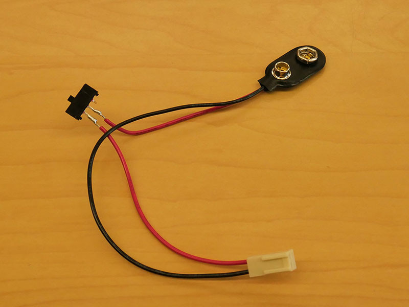 Battery clip and switch wiring for power controlFigure 15
 -
Final Circuit Assembly: The completed circuit should fit within the 3D-printed case as shown in Figure 16. Figure 17 provides a clearer view of component placement without the wire clutter.
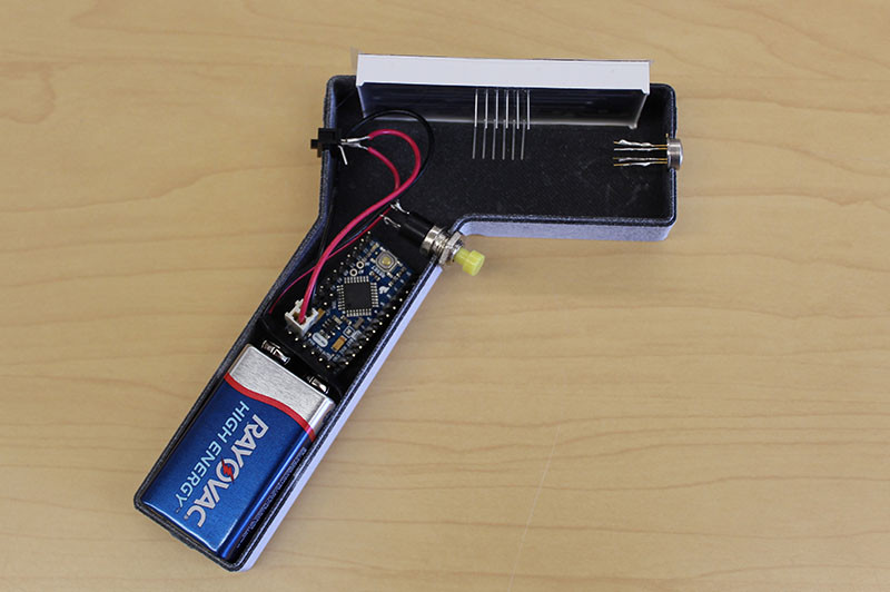 Component placement within the case without wires for clarityFigure 17
Step 4: Program the Arduino Board
You have two options to program the Arduino Pro Mini for your “UMaine print clip” thermometer: using an FTDI board or using an Arduino Uno.
Before uploading the code, double-check the IRThermometer program to ensure the I/O pin assignments match your wiring.
Programming Methods:
-
Using an FTDI Board (Easier Method):
- Slide the FTDI board onto the correct pins of your Arduino Pro Mini. The Arduino software should automatically recognize the connected board.
-
Using an Arduino UNO (Without FTDI Board):
- CAREFULLY remove the ATmega328 chip from the Arduino UNO board.
- Connect the UNO’s pins to the Pro Mini pins as follows:
- UNO 5V to Pro Mini VCC
- UNO GND to Pro Mini GND
- UNO TX to Pro Mini TX0
- UNO RX to Pro Mini RX1
- UNO Reset to Pro Mini RST
- Open the Arduino software and select “Tools” > “Board” > “Arduino Pro or Pro Mini”.
- Upload the
IRThermometerprogram to the Pro Mini.
Testing and Calibration:
- TEST: After programming, power the thermometer. Hold the sensor 1-2 inches from your forehead and press and release the pushbutton. The display should show your temperature. Repeat this a few times. Test on another person if possible.
- CALIBRATE: If the thermometer consistently reads slightly high or low, calibration is necessary. In the Arduino code, find the
tempOffsetvariable (located near the beginning of the code, marked with asterisks******). The default value is 7. Adjust this value (increase to lower readings, decrease to raise readings) until the thermometer reads approximately 98.6°F (37°C) for a healthy individual. Re-upload the adjusted code to the Arduino.
Remember, you only need one FTDI board or Arduino Uno to program multiple thermometers. Once programmed, these programmer boards are no longer needed for operation.
IMPORTANT: Program the Arduino BEFORE final assembly. Once fully assembled and clipped into the case, accessing the Arduino for reprogramming can be challenging.
Step 5: Final Assembly and Case Closure
Once both halves of the 3D-printed case are ready and the Arduino is programmed, proceed with final assembly.
Ensure the two case halves fit together correctly. Carefully install the electronic components into their designated openings in the case. You might need to gently file some openings for a perfect fit. All components should fit snugly within the case for a robust “UMaine print clip” thermometer. Finally, clip the two halves of the 3D-printed case together to enclose the electronics.
Step 6: Final Testing
Turn on the “UMaine print clip” thermometer using the power switch. The display should initially show “0”. Press and hold the button; during this time, random segments might light up. Upon releasing the button, the display will show the measured temperature. It’s advisable to repeat the temperature measurement a few times for a more consistent reading.
This infrared thermometer is a project developed by the VEMI Lab at the University of Maine. For any questions or inquiries, please contact VEMI Lab.