When it comes to 3d Printing Design, achieving optimal results often lies in understanding and applying clever techniques to overcome common challenges. This article explores practical design considerations to enhance your 3D printed parts, focusing on holes, threads, and text, ensuring your creations are both functional and aesthetically pleasing.
Mastering Horizontal Holes in 3D Printing
One frequent issue in 3D printing is drooping filament when creating horizontal holes. Traditional circular holes can suffer from this, particularly at the top of the hole where there’s no support during printing. Infographics, like those from Billie Ruben, suggest alternative shapes such as teardrop, hexagonal, or square holes to mitigate this problem. These shapes are often effective in preventing drooping, especially hex and square holes, and square holes rotated 45 degrees for larger sizes to avoid bridging issues. As 3D printing technology advances, even higher-order polygons may become viable options for clean horizontal holes.
However, there’s another surprisingly effective solution: modeling threads directly into horizontal holes. This technique leverages the threads themselves to support the overhanging material during printing, similar to the concept of arc overhang supports. Initially, one might expect to need to tap these printed threads to make them functional. However, closer inspection of slicer previews reveals that the threads eliminate the overhang issue, leading to clean prints capable of directly accepting screws. This method streamlines the process and can be a significant time-saver.
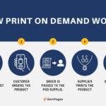
 Close-up view showcasing ISO metric thread tolerances, highlighting the differences between tolerance classes like G and H for thread fitting.
Considerations for Modeling Threads in 3D Design
While modeling threads offers advantages, it’s computationally intensive. Therefore, it’s advisable to add threaded holes towards the end of your 3D design workflow. Software like FreeCAD can be sensitive to thread modifications, potentially altering edge names and causing issues related to the “topological naming problem.” Changing a plain hole to a threaded one mid-design can disrupt topologically fragile models, especially those not built upon datum features.
When designing threads, especially in FreeCAD, you’ll encounter thread tolerance classes. Understanding these classes is crucial for achieving the desired fit. “G” threads are looser than “H” threads, and higher numbers within each class indicate looser fits. Experimentation with your specific 3D printer is key to determining the ideal tolerance class for easy screw insertion versus a tighter, lock-nut style fit. This calibration ensures your 3D printed threads function as intended without excessive tightness or looseness.
While heat-set inserts are often considered for durability, it’s worth noting that threads directly printed in plastic can be surprisingly robust for applications involving infrequent assembly. Plastic threads may not withstand as many cycles as metal threads, making heat-set inserts preferable for parts frequently disassembled and reassembled. However, for parts intended for single or occasional assembly, 3D printed threads offer a viable and efficient alternative.
Tapered Designs for Snap-Fit Assemblies
Beyond threads, tapers present another excellent method for creating parts that assemble securely yet can be disassembled. Tapers are widely used in machine tools due to their precision and holding power. Wide taper angles are “self-releasing,” allowing for easy separation, while narrow angles are “self-holding,” creating a firm connection. A 2° taper angle strikes a good balance for 3D printed parts, providing a secure fit with the ability to be taken apart.
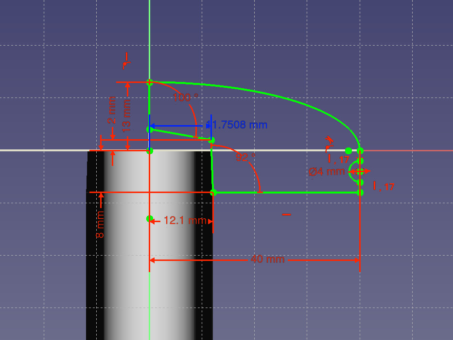
The effectiveness of tapers in 3D printing is demonstrated in designs like a 3D Printed Darning Mushroom. In such designs, accounting for layer thickness and print variations is crucial. For instance, adding 0.1mm to the radius of the receiving hole and extra depth (around 2mm) provides tolerance for consistent assembly. Examining the sketches of mating parts in taper-based designs reveals how these adjustments facilitate reliable snap-fit connections.
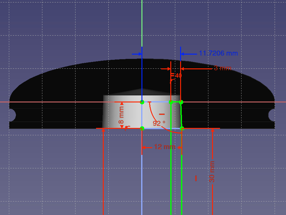
 Exploded view of a 3D printed darning mushroom design, showcasing the tapered components designed for snap-fit assembly.
 Cross-section view of the 3D printed darning mushroom assembly, highlighting the 2° taper angle used for secure and releasable connection.
Text in 3D Prints: Embossing vs. Extrusion
When incorporating text into 3D prints, the choice between embossing (inward text) and extrusion (outward text) impacts both aesthetics and readability. While embossing is often recommended for simplicity, extruded text offers advantages, particularly when color contrast is desired. For top layers, extruded text can be easily colored using a sharpie or similar marker after printing. This technique is effective for labeling parts, such as numbering gears in a hypotrochoid graphic drawing set. While PETG prints may benefit from a quick heat gun treatment to remove stringing before coloring, the resulting colored extruded text is noticeably clearer than embossed text, especially when comparing small text sizes.
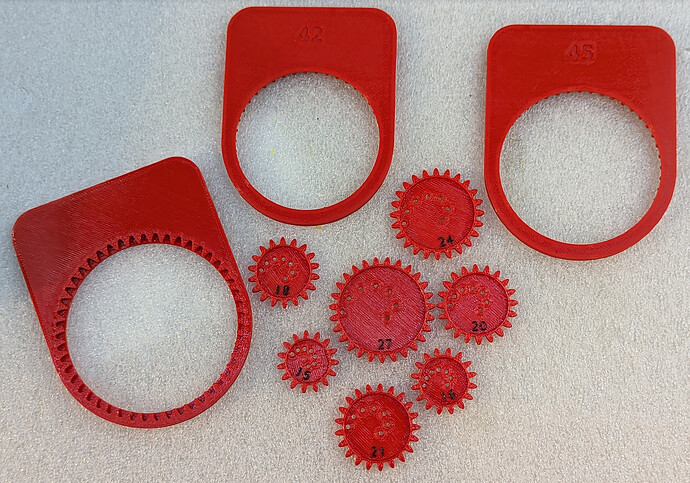 Close-up image comparing embossed text (numbers "42" and "45") with colored extruded text on 3D printed gears, illustrating the improved clarity of extruded text, especially after coloring with a sharpie.
For projects demanding a refined finish, such as personalized frames, sharpie-toned extruded text on vapor-smoothed ABS prints can achieve a remarkably crisp and professional look. This approach provides a visually striking way to add dates, names, or other important information directly onto 3D printed objects.
By implementing these 3D printing design considerations – from mastering hole shapes and threads to utilizing tapers and strategic text placement – you can significantly elevate the quality and functionality of your 3D printed creations.