
Composite materials represent a fascinating class of substances engineered by combining two or more distinct materials to achieve properties that surpass those of the individual components. While everyday examples like concrete and particleboard fit this definition, in engineering, the term “composite” often refers to materials reinforced with fibers. Carbon fiber, fiberglass, and Kevlar are prominent examples of such reinforcing fibers widely utilized across industries. As previously discussed in “Physics of 3D Printing,” individual fibers, likened to spaghetti strands, are thin, brittle, and easily breakable when bent. Consequently, these fibers are almost always employed in conjunction with a matrix material to bind them together, forming optimized shapes like sheets, rods, or custom molds. This binding allows for load distribution and dispersion along the lengths of numerous fibers, creating robust structural elements.
 a fiberglass layup within a mold
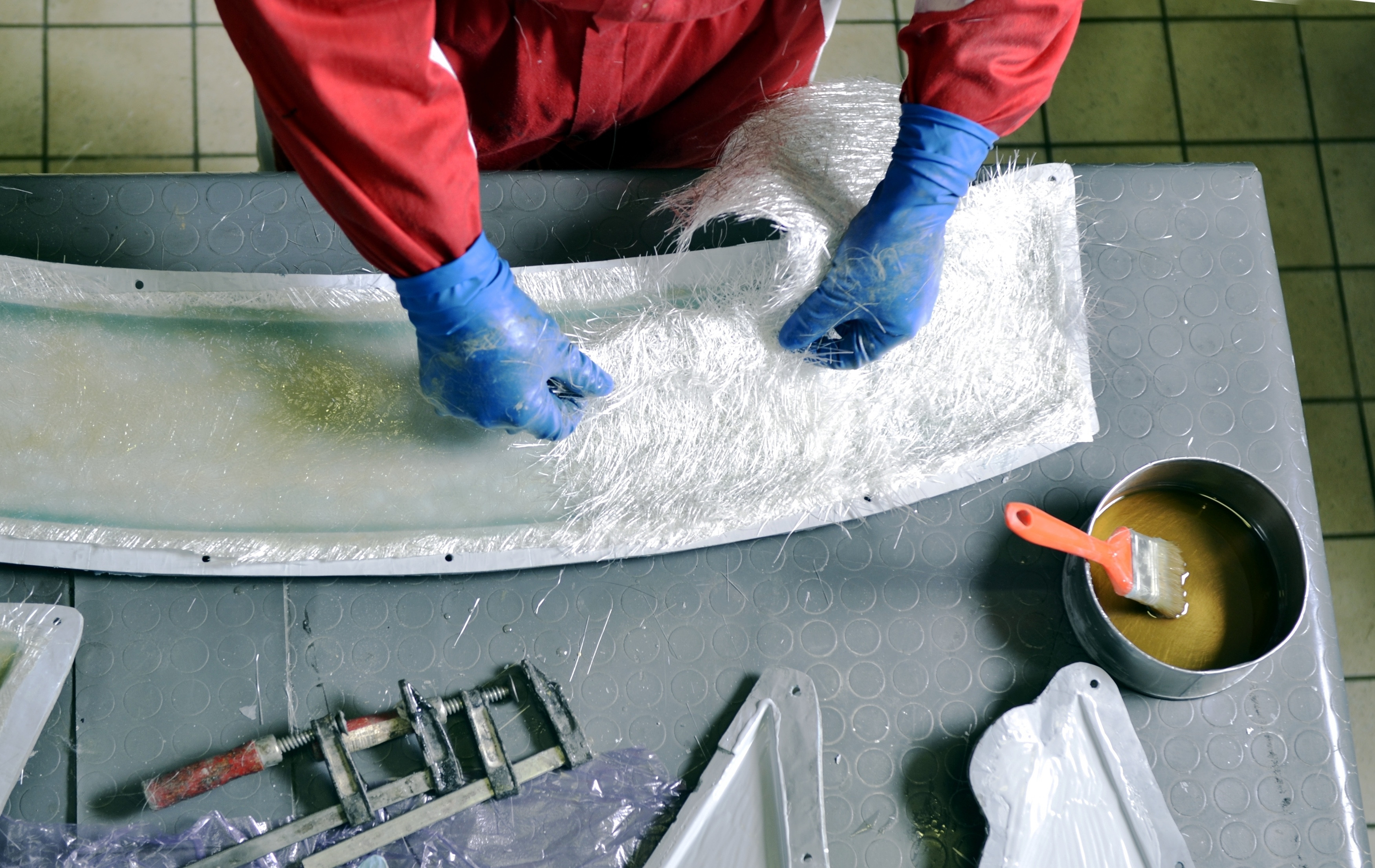
Fiberglass strands are carefully positioned within a mold and then cured with a thermoset resin to create a composite part.
Carbon fiber stands out due to its exceptional strength-to-weight ratio, making it highly desirable for manufacturing lightweight yet strong components. These fibers are composed of carbon atoms arranged in a crystal structure aligned along the fiber’s length, providing remarkable tensile strength. Traditionally, thermoset resins serve as the bonding agent, setting the fibers into a desired shape, often around a matrix material like foam. This technique allows for the creation of sandwich panels, where foam is encased between fiber weave sheets and cured with resin. Within the realm of 3D printing, carbon fiber manifests in two primary forms:
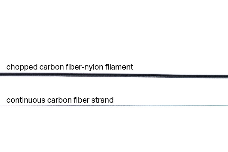
Chopped Fibers: These are short segments of fibers, typically less than a millimeter long, mixed into conventional thermoplastics. This mixture forms what is known as a filled plastic, suitable for printing using the Fused Deposition Modeling (FDM) process.
Continuous Fibers: This method necessitates a specialized 3D printing technique where continuous fiber strands are coated with a curing agent and embedded into a thermoplastic matrix, which is extruded through a secondary print nozzle. This process is known as Continuous Fiber Fabrication (CFF).
 carbon fiber 3D printing types
An illustration showcasing the two main types of 3d Printed Carbon Fiber: chopped fiber filament (top) and continuous carbon fiber strand (bottom).
Regardless of the fiber addition method, incorporating fibers enhances a part’s strength and other material properties. However, the degree of improvement varies based on the fiber type and application method. Generally, continuous carbon fiber 3D prints exhibit superior strength compared to those made with chopped carbon fiber due to the load distribution advantages of continuous fibers.
Exploring Chopped Fiber 3D Printing Materials
Chopped fiber filled plastics represent the most prevalent type of composite 3D printing materials. Among these, chopped carbon fiber is the most commonly used, where small carbon fiber pieces are blended with standard 3D printing plastics such as nylon, ABS, or PLA. This “filling” acts as a material performance enhancer for thermoplastics. Similar to how concrete strengthens cement, the fibers in chopped carbon fiber composites bear a portion of the part’s stresses, improving the properties of typically weaker base plastics. Furthermore, the incorporation of carbon fiber enhances the thermal stability of mechanical properties, widening the operational temperature range and improving the predictability of material behavior in both high and low-temperature environments.
 chopped carbon fiber 3D printing under microscope
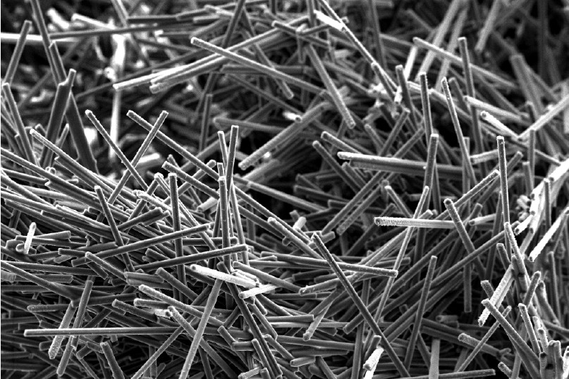
A microscopic view of chopped carbon fibers utilized in 3D printing, captured using a Scanning Electron Microscope (SEM).
These fibers are finely chopped and mixed into the plastic before being extruded into filament spools for use with material deposition-based 3D printers. The 3D printing process remains largely unchanged as the fibers are suspended within the thermoplastic. Consequently, the material undergoes the same heating, extrusion, and cooling process as conventional FFF 3D printing. Chopped composite 3D printing materials effectively upgrade standard plastics that may lack certain desired properties. In the case of carbon fiber, the fibers enhance the part’s strength, stiffness, and dimensional stability, resulting in higher-performance components compared to those made from the base plastic alone.
 chopped carbon fiber 3D printing material
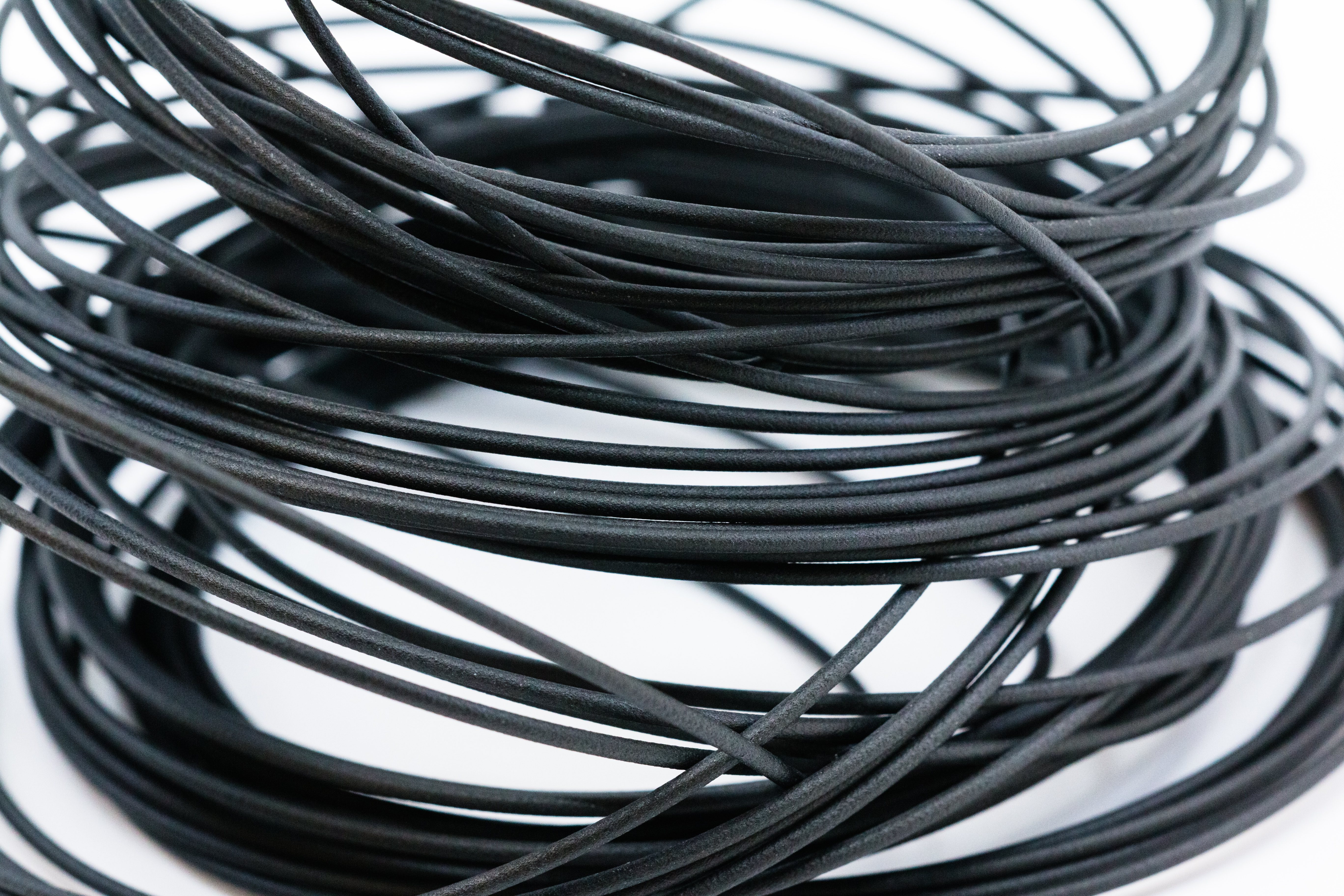
Chopped carbon fiber 3D printing materials offer ease of use similar to standard 3D printing plastics, while significantly improving material properties.
The concentration and length of chopped fiber segments significantly influence the strength and quality of the final part. Different manufacturers employ varying ratios of fiber in their plastic blends, leading to materials with diverse strength characteristics. Below a certain fiber content threshold, the fibers primarily enhance surface finish and print quality. Conversely, exceeding this threshold with a higher concentration of longer fibers yields a stronger material but may compromise surface finish and part accuracy due to a reduced percentage of plastic in the overall mixture. The thermoplastic matrix is crucial for the printability of the material; thus, there are inherent limits to the maximum achievable strength in chopped fiber composites.
Unveiling Continuous Fiber 3D Printing
Continuous fiber 3D printing introduces continuous strands of fiber reinforcement into the part, reminiscent of the fiber strands discussed earlier, enabling the creation of parts with metal-like strength at a significantly reduced weight. Employing a dual-nozzle system, this process involves building the matrix material from a thermoplastic while simultaneously embedding continuous fiber strands into the part. This method, known as Continuous Fiber Fabrication (CFF), represents a significant advancement in composite 3D printing.
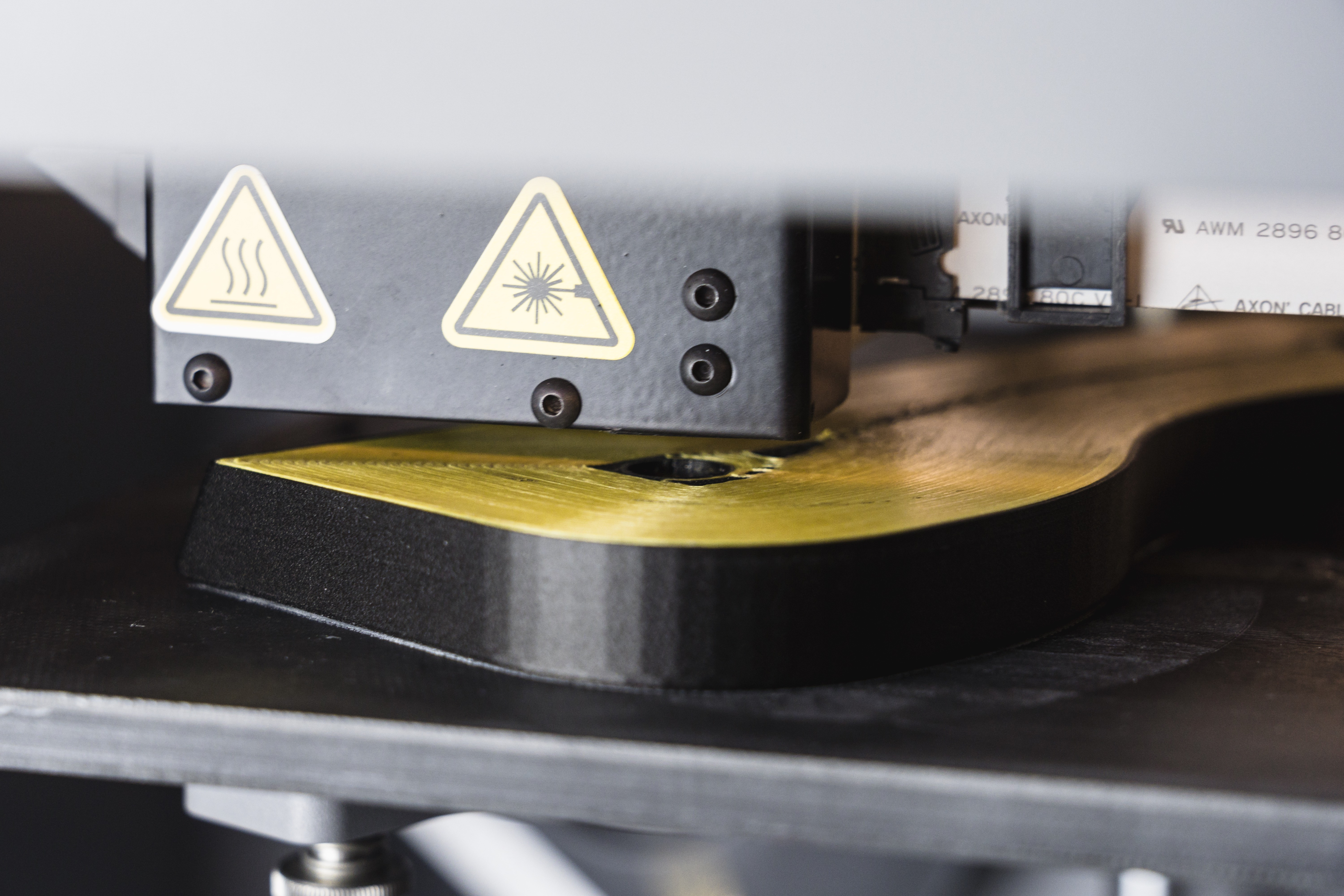 Continuous Kevlar strands are ironed into this part to increase its impact resistance with a composite fiber printing nozzle. A thermoplastic matrix material forms the skin and core of the part.
Continuous Kevlar strands being integrated into a 3D printed part to enhance impact resistance using a composite fiber printing nozzle. The part’s skin and core are formed from a thermoplastic matrix material.
The strength of CFF lies in the continuity of the reinforcing strands. Unlike chopped fibers, continuous strands can effectively absorb and distribute loads across their entire length. When embedded within a thermoplastic matrix, these parts can withstand higher loads and absorb greater impacts. This capability allows continuous fiber 3D printed parts to achieve the strength of metal components while maintaining a fraction of the weight.
 Continuous carbon fiber 3D printing explained
Continuous fibers act as the backbone of a 3D printed part, effectively distributing loads along their length, rather than solely relying on the plastic matrix.
The CFF 3D printing process comprises two steps per layer. First, a thermoplastic material is extruded to create the infill and outer shells of the part, forming the “matrix” of the composite. Next, continuous fiber strands are embedded into this matrix, fusing with the thermoplastic through a compatible resin coating. This layer-by-layer process builds the fibers into the structural backbone of the 3D printed part, while the thermoplastic acts as a skin. This process parallels the reinforcement of concrete using rebar.
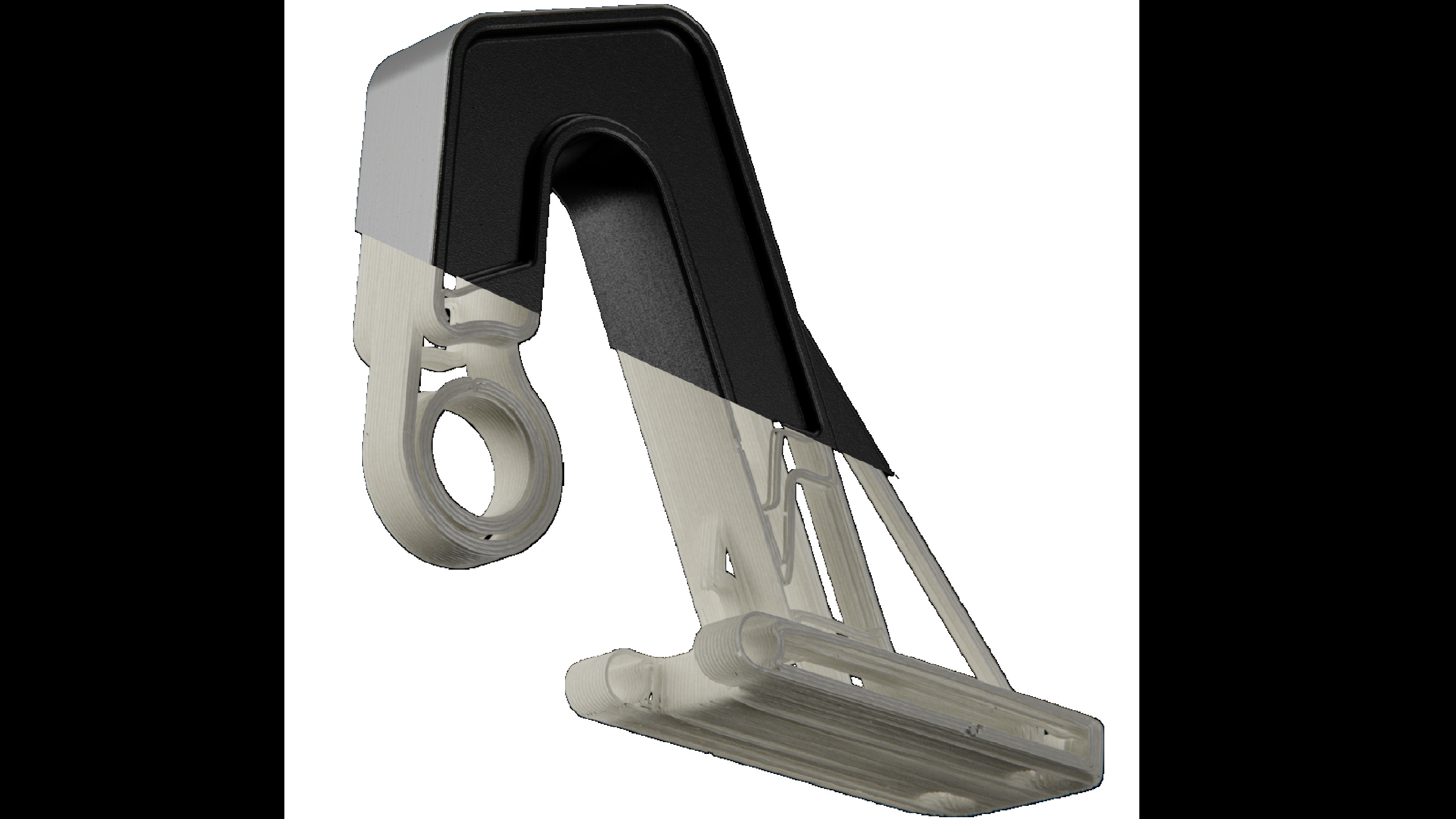
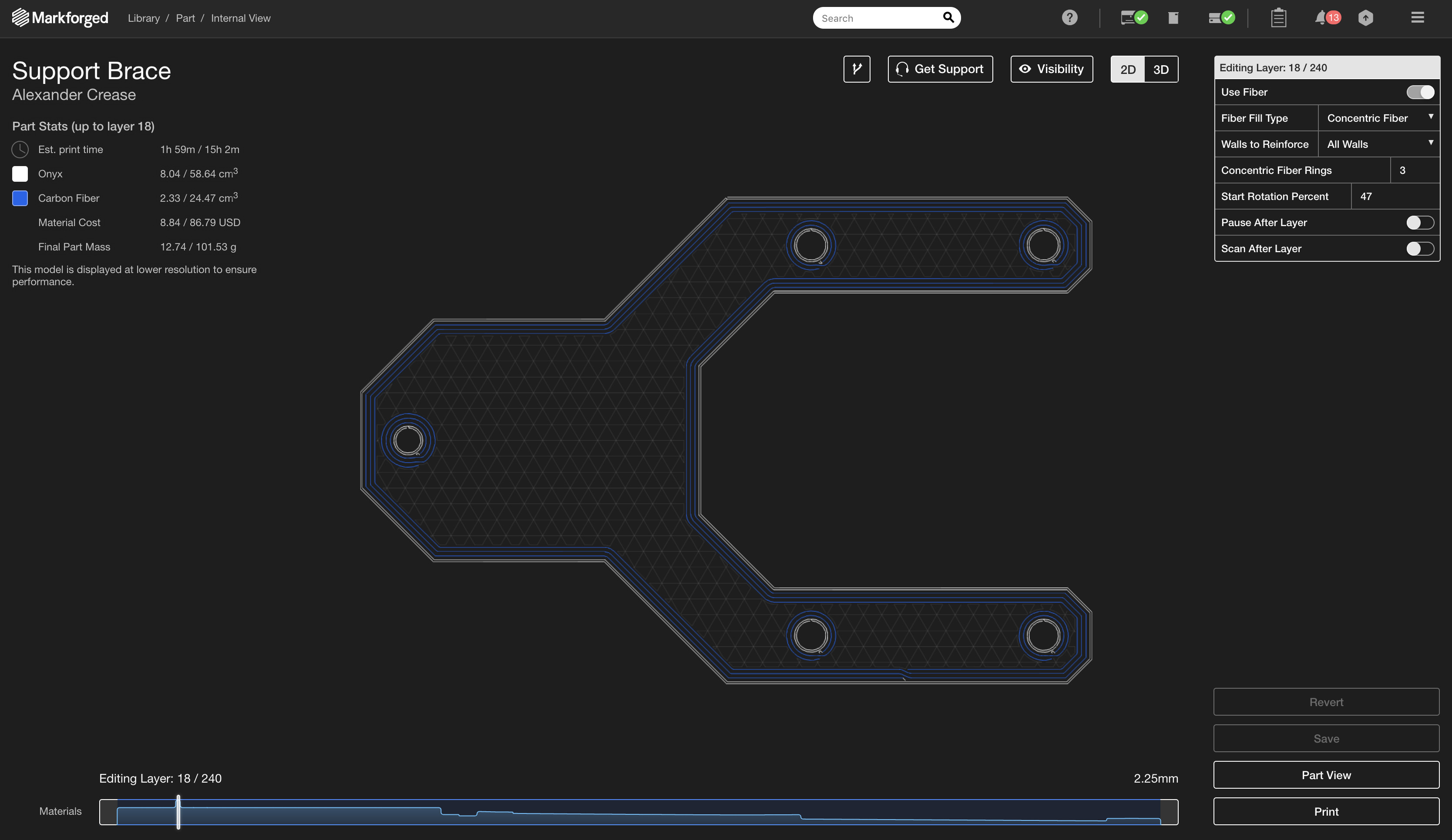 The fibers form the "backbone" of the part and can be laid down in specific patterns to optimize a part’s strength for its weight and material consumption.
The fibers form the structural “backbone” of the 3D printed part and can be strategically placed in specific patterns to optimize strength, weight, and material consumption.
Fibers can be strategically placed in specific areas based on anticipated load conditions, concentrating strength precisely where needed. This targeted reinforcement distinguishes continuous fiber 3D printing from standard deposition-based methods, including those using chopped fibers, which typically result in a uniform distribution of properties throughout the entire part. Various fiber reinforcement options are available to cater to different loading conditions and performance requirements.
Markforged 3D printers offer a selection of fiber materials, enabling users to tailor the strength characteristics of their reinforced parts:
Carbon Fiber: Known for its stiffness and strength, carbon fiber emulates the performance of 6061 Aluminum. It is ideal for creating lightweight components capable of supporting substantial loads.
 This 3D printed carbon fiber can match the strength of aluminum when continuous. Both are supporting a 27.5 lb load.
This 3D printed continuous carbon fiber part demonstrates strength comparable to aluminum while supporting a 27.5 lb load.
Fiberglass: Fiberglass offers a robust and cost-effective reinforcement solution with a degree of compliance. It enhances part strength beyond that of unreinforced plastics and provides an accessible entry point into reinforced 3D printing.
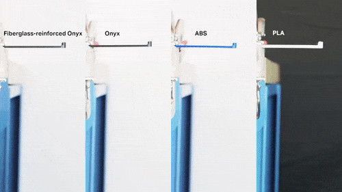 Fiberglass is a robust 3D printing fiber option, exceeding the strength of chopped fiber, ABS, and PLA when supporting a 7.5 lb weight.
Fiberglass presents a durable 3D printing fiber choice, surpassing the strength of chopped fiber, ABS, and PLA, as shown by its ability to support a 7.5 lb weight.
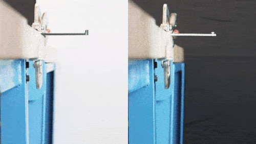
Kevlar: Kevlar exhibits high toughness and exceptional shock resistance, making it well-suited for applications involving shock loading and high-impact conditions. It is characterized by its ability to bend rather than fracture under stress.
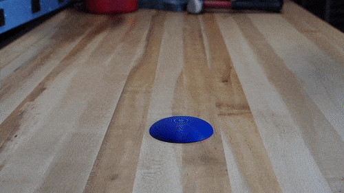 a 3D printing impact test
An impact test showcasing the shock-loading performance of PLA, ABS, and Kevlar reinforced 3D printed parts when subjected to hammer blows.
High Strength High Temperature (HSHT) Fiberglass: This specialized fiberglass variant maintains its strength and stiffness at elevated temperatures due to its high heat deflection temperature. Its heat resistance enables it to perform reliably in more extreme operating environments.
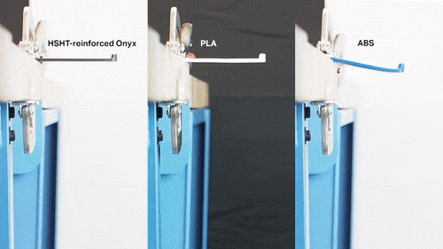 This test was performed after heating each beam to 300 degrees Fahrenheit in an oven. HSHT does not lose strength at high temperatures, so it still supports the 5 lb load.
This high-temperature test demonstrates that HSHT Fiberglass retains its strength and supports a 5 lb load even after being heated to 300 degrees Fahrenheit.
By strategically selecting different fiber types to match specific material requirements and precisely controlling fiber placement layer by layer, users can effectively tailor the performance and behavior of their 3D printed parts. This customization capability represents a key advantage of continuous 3D printed composites over chopped fiber materials. Continuous fiber 3D printing not only yields stronger parts but also facilitates the production of components optimized for their intended applications.